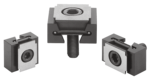
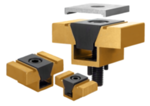
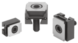
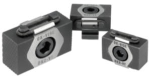
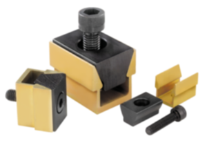
Wedge clamp double tool steel hardened 04527-12
- Ideal for horizontal and vertical series clamping
- For high clamping forces
- Can be used both in a tapped hole and in a T-slot
- With positive down force
Sales unit
PLN997.58
plus sales tax
Added to your shopping cart
Designation
Wedge clamp
Version 1
double
Version 2
for tapped hole
Product type
pull-down clamping
Main
material
tool steel
Surface finish
body
hardened
Component
material
tool steel
Surface finish
component
hardened and black oxid finish
B=Width
41
D=Thread
M12X60
A
max.
49
A
min.
42
Application
blanks
B1
30
C
36
Clamping
force
max. kN
40
E
5
G
M12
Kind of fastening
thread
Tightening
torque
max. Nm
85
~ CONFLICT MINERALS 3TG status
not yet identified
~ CP65 substance 2 cancer
soots, tars, and mineral oils
~ PFAS free?
yes
~ REACH SVHC-free?
yes
~ RoHS conformity
yes, without exemption
~ TSCA 6(H) conformity
yes
Description
Material
Body and jaw segments tool steel.
Version
Body hardened.
Jaw segments hardened (49-51 HRC) and black oxidised.
Wedge faces ground.
Jaw segments hardened (49-51 HRC) and black oxidised.
Wedge faces ground.
Note
Because of their compact design, the double wedge clamps are especially suitable for horizontal and vertical multiple clamping. The hardened and ground wedge surfaces make high clamping forces possible.
Optionally, the appropriate wedge clamp can be mounted either in a grid hole or T-slot. Inserting a socket head screw DIN 912 moves the two clamping segments outwards and presses the workpieces against a fixed stop.
The so-called “draw-down effect” is caused by the double wedge of this version.
Travel acc. to order No.:
04527-12 = ±1.0 mm
04527-16 = ±1.5 mm
Drawing reference
D) DIN 912 cap screw
1) Wedge clamps
2) Workpiece
3) Fixed stop
1) Wedge clamps
2) Workpiece
3) Fixed stop
Important note on downloading CAD models
In order to download our CAD models, you must log in first. If you have not created an account yet, please register under "My Account" (right side of the screen) and follow the instructions.
Other customers also bought