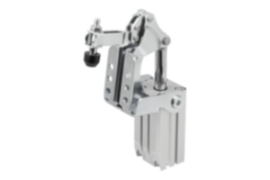
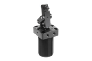
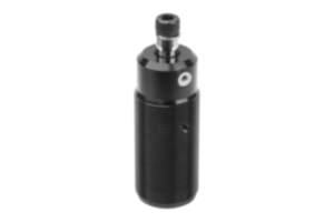
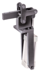
Swing clamp pneumatic aluminium black anodised 05610-10-150
- Automatable
- Universal fastening possibilities
- Swivels to right and left
- Double-acting
Sales unit
PLN1,963.28
plus sales tax
Added to your shopping cart
Designation
Swing clamp
Version 1
pneumatic
Version 2
screw-on with flange
Form definition
swivel to the right
Main
material
aluminium
Surface finish
body
anodised
Main
colour
black
Component
material
steel
Surface finish
component
hard chromed
B=Width
75
D=Thread
M65X1,5
H=Height
110
A
80
A1
90
A2
42,5
A3
32
B1
58
B2
100
D1
M10
D2
20
D3
8,5
D4
G1/8
F1
N
1020
H1
167
H2
80
H3
30
H4
25
H5
11
H6
10,5
H7
25
S1
16
S2
16
Size
50
Travel
S
32
UNSPSC Code
31162800
~ CONFLICT MINERALS 3TG status
not yet identified
~ CP65 substance 2 cancer
carbon-black extracts
~ PFAS free?
not yet identified
~ REACH SVHC-free?
yes
~ RoHS conformity
yes, without exemption
~ TSCA 6(H) conformity
yes
Description
Material
Body aluminium.
Piston steel.
Piston steel.
Version
Body silver anodised.
Piston hard chrome-plated
Piston hard chrome-plated
Note
Screw-in pneumatic swing clamps with flange find use where low clamping forces suffice and where the clamping point has to be cleared to enable placing or removing the workpiece.
The design enables space saving installation. The screw-in bolt can be used to adjust the height of the swing clamp. The clamp is suitable for a sunken mounting in a fixture. The compressed air port for the swing clamp is in the flange.
Due to the double-acting function of the clamp, pressure is used to move the piston downwards and upwards.
The total travel of the swing clamp consists of the swing travel and the clamping travel. At the start of the clamping process, the clamping arm performs a 90° swing movement. When this movement is completed, the linear down clamping travel is carried out. The workpiece must only be clamped using the clamping travel.
The swing clamp must not be constrained in its swinging action. F1 = at 6 bar max. permitted operating pressure.
The screw-in swing clamp with flange can be fastened from above or below using a DIN 70852 slotted round nut (07590-05). Another option is to fasten the swing clamp to the fixture from above using four cap screws.
The swing clamp must only be operated using lubricated air.
The fastening holes in the flange have the same dimensions as those in the threaded flange 05610-20.
The screw and the lock washer for fastening the clamping, which is available as an accessory, are supplied.
Clamping arm and slotted round nut are not supplied.
Drawing reference
1) Clamping
2) Releasing
3) Swing travel
4) Clamping travel
5) Relaxed
6) Tensioned
7) Left swinging
8) Right swinging
2) Releasing
3) Swing travel
4) Clamping travel
5) Relaxed
6) Tensioned
7) Left swinging
8) Right swinging
Accessory
05620 Clamping arm for swing clamp.
07590-05 DIN 70852 slotted round nut.
07590-05 DIN 70852 slotted round nut.
Important note on downloading CAD models
In order to download our CAD models, you must log in first. If you have not created an account yet, please register under "My Account" (right side of the screen) and follow the instructions.
Other customers also bought